Facility Capabilities & Standards
1.0 PRINCIPAL OPERATIONS
The facility operates as a technical cell consisting of a Mechanician and a Manufacturing Engineer. Structured for experimental kinetic, robotic, and prosthetic mechanism development, the cell translates kinematic concepts into physical hardware—applying physical intuition and mechanical logic across design, CAD modeling, CNC machining, precision setups, and mechatronic assembly benches.
Operational capacity is committed to a single project until delivery to ensure technical focus and execution integrity. Outside of active client contracts, the facility operates as an independent R&D workshop to develop proprietary mechanisms, motion-transition models, and fabrication methodologies.
2.0 Operational Specifications
| Area | Description |
|---|---|
| Intake Scope |
Fabrication and assembly of individual components, robotic frameworks, and kinetic or prosthetic mechanisms. The facility processes projects at any level of readiness, from initial concept layouts to completed designs requiring physical execution. Internal workflows handle the mechanical lifecycle of custom assemblies—including joint integration and the post-machining of additive components, castings, and weldments. Secondary operations include coordinated thermal processing and technical surface finishes, such as heat-treating and anodizing.
Capabilities extend to the modification, optimization, and mechanical refinement of kinetic sub-assemblies and prototype frameworks compatible with the facility's 15-by-30-foot Mechanical Assembly Bay. |
| Component & Mechanism Development | Collaborative review is available to iterate solutions and resolve mechanical risks prior to fabrication. Work encompasses component geometry refinement, interface configuration, the generation of 3D models, and the identification of tolerance stack-up issues. |
| Capacity & Throughput | Quantities are limited to small-batch and prototype lots to preserve a direct, uncompromised workflow. |
| Process Capabilities | The cell integrates CNC milling and turning, and 3D printing with secondary machining. Internal capabilities include soldering and mechatronic integration for functional mechanisms. |
2.1 Scope Exclusions
Weapons and firearms are excluded from project intake.
Federally regulated medical, aerospace, and automotive projects are restricted to early-stage concept development and experimental research. Certified flight-critical or life-critical fabrication is excluded.
All facility visits and technical consultations require a scheduled appointment.
3.0 Technical Infrastructure
Design & Simulation
-
Software & Platforms
- 3D Mechanical CAD software
- Simulation and analysis tools
- CAD/CAM with 3D surfacing capability
Fabrication & Machining
-
CNC Systems
- CNC machining center
- CNC turning center
- Formlabs SLA printing systems
-
Manual & Support Equipment
- Bridgeport milling machine
- 13" x 40" manual lathe
- Welding equipment
- 12" horizontal bandsaw
- 12T arbor press
- 20T H-frame press
Mechanical Assembly Bay
- • 15' × 30' footprint with 14' clear ceiling height
Metrology & Verification
- Grade AA granite surface plate
- Granite square
- Certified gauge blocks
- Test indicators
- Accuracy threshold: ±0.0002"
Mechatronic Integration
-
Diagnostic & Prototyping Equipment
- Digital storage oscilloscope
- Variable DC power supplies
- Benchtop digital multimeters
- Data acquisition (DAQ) modules
- Precision wire-processing and crimping tooling
- Component-level ESD-safe workstations
- Electrical testing benches
- Soldering stations
4.0 Laboratory Environments
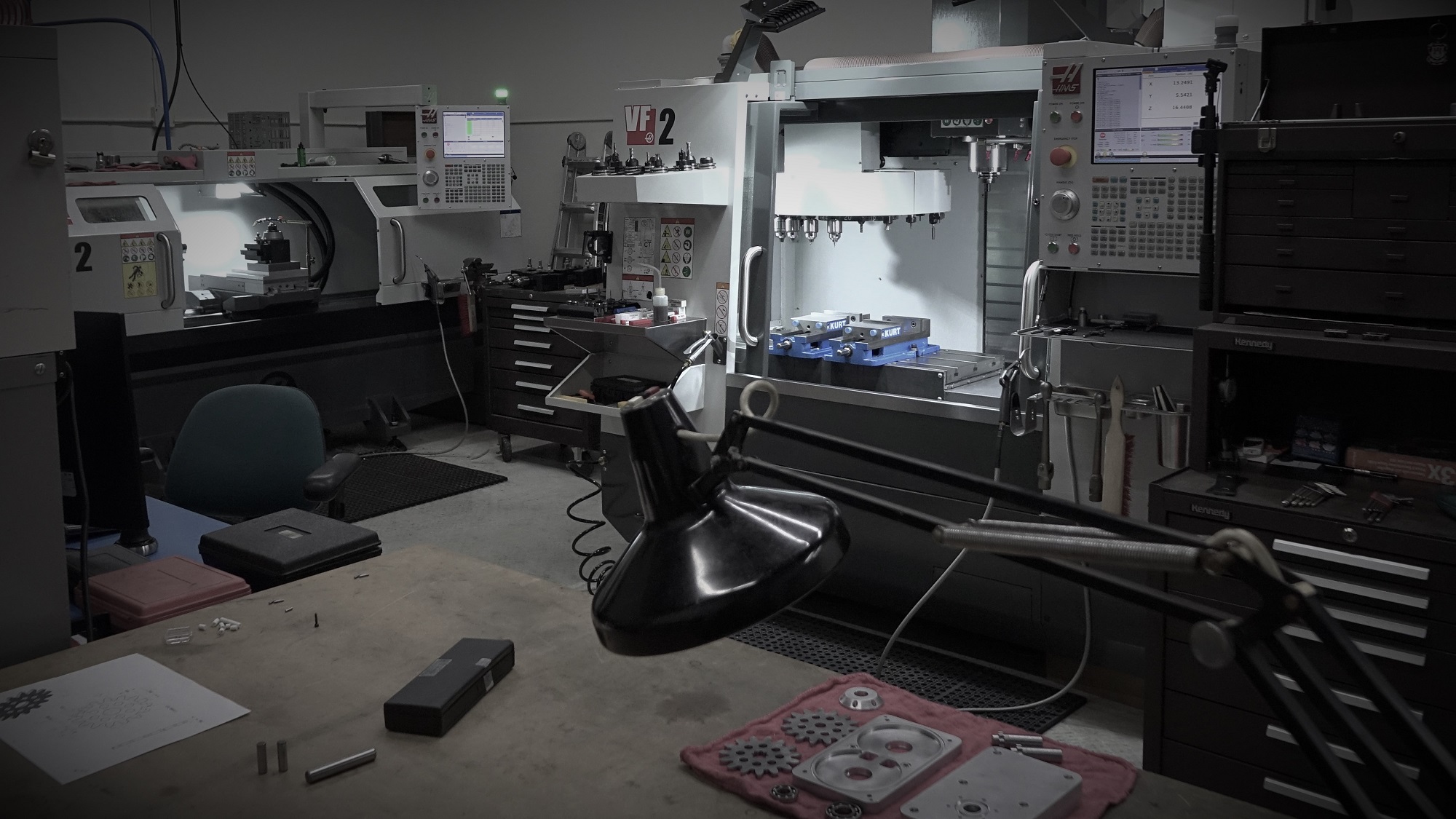
CNC Fabrication Cell
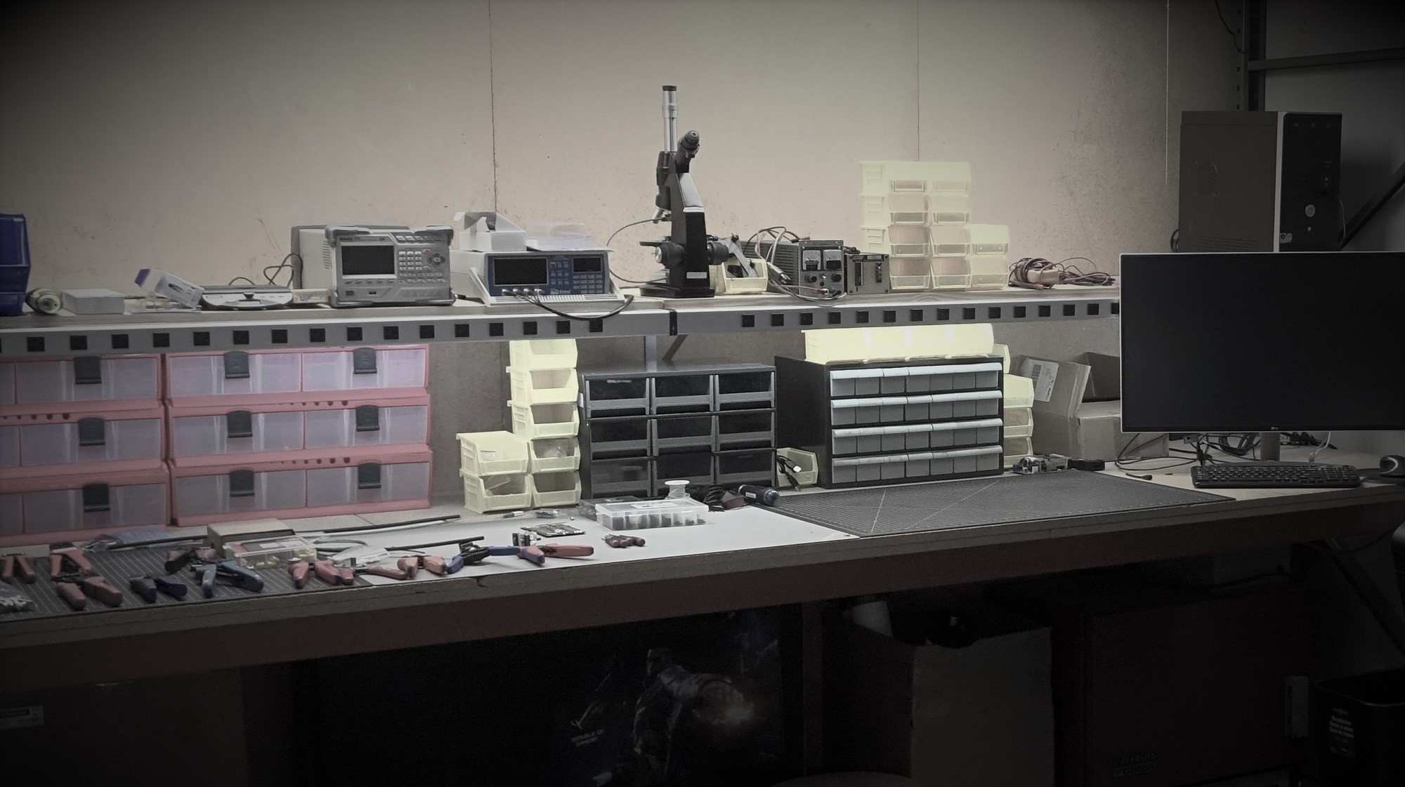
Soldering & Electronics
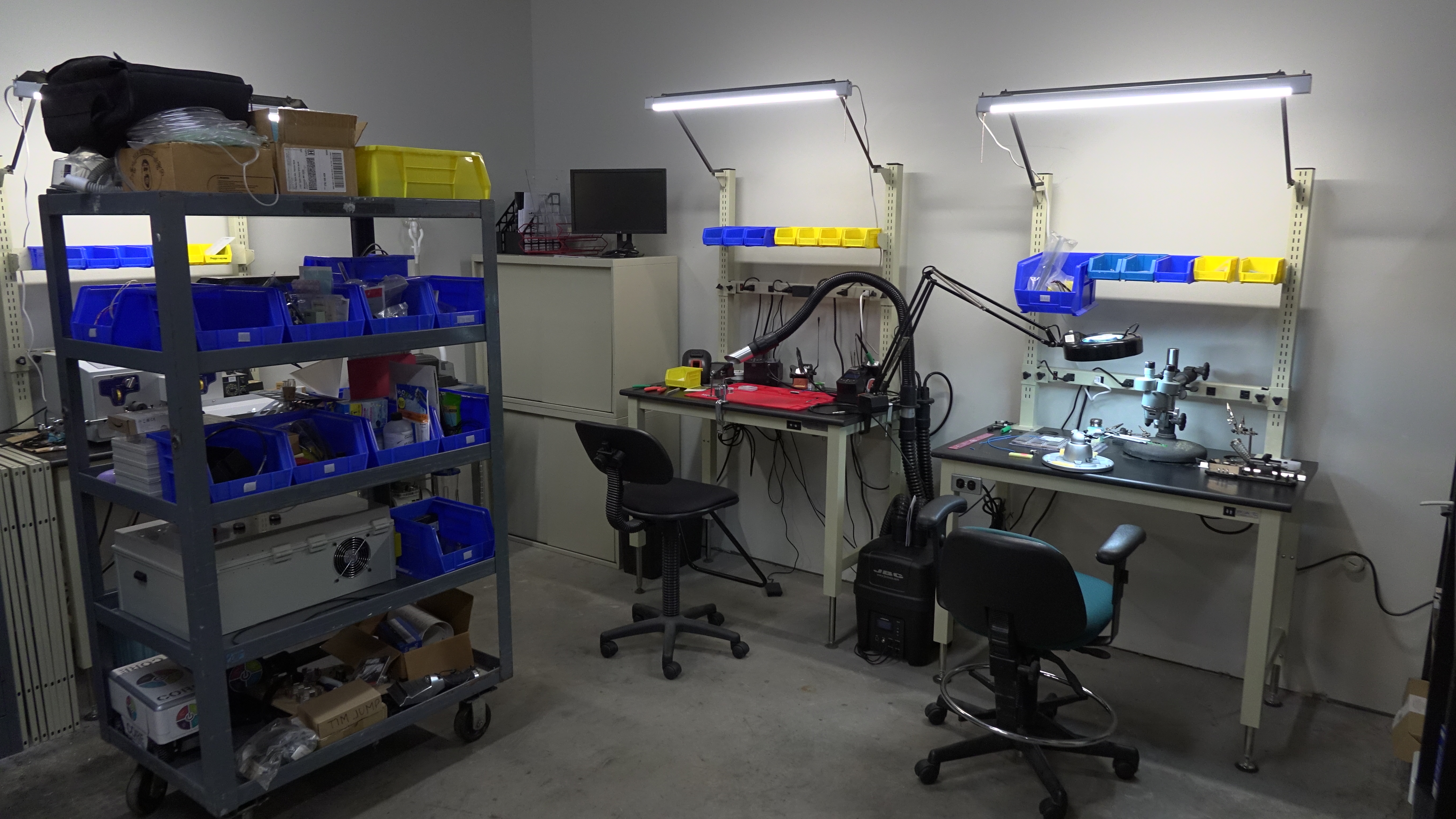
Mechatronic Assembly & Testing
Facility Exterior - St. Louis Park, MN

5.0 Project Framework
5.1 Confidentiality & IP Protection
If your project involves sensitive technical data, proprietary 3D CAD models, or detailed 2D prints, do not transmit these files prior to executing a Mutual Non-Disclosure Agreement (MNDA).
5.2 Data Submission Standards
Following the execution of an MNDA (where applicable), a 3D CAD model provided in a neutral format (STEP/.stp preferred) serves as the master geometric reference for all projects.
While 3D data is the standard for intake, the facility can provide estimates for the generation of master 3D CAD models derived from customer-supplied 2D documentation or developed via the dimensional replication of physical components. All facility-generated models are subject to final customer verification and approval prior to the initiation of fabrication.
Project data must be accompanied by 2D documentation provided in PDF format, utilizing one of the following standards:
- Fully Detailed Drawings: Complete drawing sets inclusive of Geometric Dimensioning and Tolerancing (GD&T) to define all features.
- Limited Specification Drawings: Targeted documentation focused on critical data not inherent in the 3D model, such as tapped hole specifications, high-precision tolerances, material callouts, and specialized finish requirements.
5.3 Digital-to-Physical Correlation
Prior to initiating fabrication, a standard pre-production review is conducted to ensure thorough familiarization with the digital data and its intended physical implementation.
To optimize execution, it can be helpful to provide functional context regarding the component's role within its broader assembly or operating environment. This collaborative insight allows the facility to align machining setups with your application goals, helping to economize production costs and ensure that critical mating interfaces and mechanical fitment are perfectly balanced for manufacturing.
This process simply cross-references digital geometry with material specifications and machine setup logistics to ensure a reliable transition from model to hardware. Any adjustments or opportunities for workflow optimization are coordinated transparently with the client, ensuring the final component integrates smoothly into the larger mechanism.
5.4 Material Handling
To accommodate diverse project logistics, the facility manages material acquisition through two primary streams:
- Client-Provided: Raw materials and off-the-shelf (OTS) components may be drop-shipped directly to the facility for processing, modification, or custom assembly.
- Laboratory-Procured: Materials and standard hardware can be sourced by the facility on behalf of the project, managed with separate traceability, accountability, and clear line-item invoicing.
5.5 Manufacturing Optimization & Refinement
During CNC programming and toolpath optimization, the digital master reference is precisely aligned with efficient machine execution—maximizing material integrity and achieving superior surface finish quality.
To provide maximum project value, the facility proactively identifies opportunities where optimizing specific geometries can significantly reduce machining cycle times, extend tool life, or lower production costs. These strategic manufacturing insights are presented transparently as optional, cost-saving recommendations; no modifications to the approved master geometric reference are ever executed without explicit client authorization.
5.6 In-Process Design Adjustments
To accommodate changing research and development requirements, modifications can be integrated during active fabrication or assembly phases. Upon a client request for a design adjustment, the facility identifies an optimum integration path and assesses the impact on work-in-progress components or active sub-assemblies.
Confirmed modifications require an update to the master digital reference. We will provide notice of any resulting adjustments to project logistics, costs, or delivery schedules.
5.7 Technical Intake
For Proprietary Projects: Do not include sensitive technical data or CAD models in your initial email. Please request an MNDA baseline first.
For Non-Proprietary Projects: Open prints, STEP files, and public-domain specifications may be attached directly to your inquiry.
*Note: All weapon-related hardware is strictly excluded from intake. Medical, aerospace, and automotive projects are accepted for early-stage concept development and experimental R&D only.